Overhead Workstation
Cranes
Maximize Operational Performance
with Advanced Overhead Crane Solutions
For the Safe, Productive, Ergonomic Handling of All Overhead Lifting Requirements.
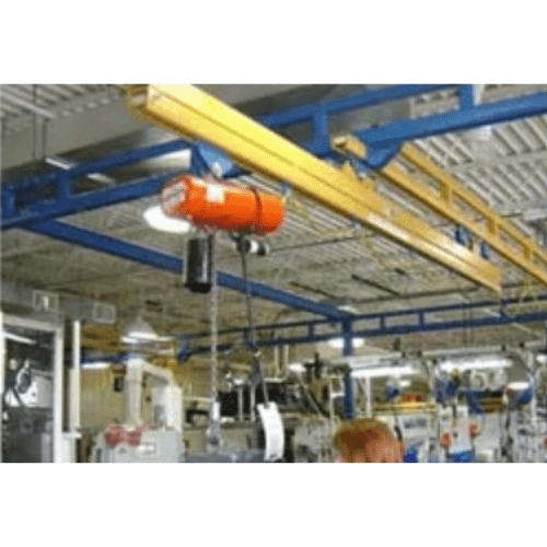
More and more businesses are choosing the enclosed track workstation crane system. As an innovator and leader in the industry, ASE provides a wide variety of overhead workstation crane solutions. Our work station systems include free standing work station bridge cranes (covered in the following pages), ceiling mounted bridge cranes, monorails, and work station jib crane. And we’re also a leading manufacturer of high-performance manual and motorized jib cranes; all this, plus quick delivery and the industry’s best warranty. (250-lb to 4,000-lb bridge capacities, 2’ to 34’ bridge lengths, 10’ to 100’+ runway length and 10’, 12’ & 14’+ trolley saddles heights)
Overhead Workstation Cranes:
Boost Efficiency and Safety in Your Workspace
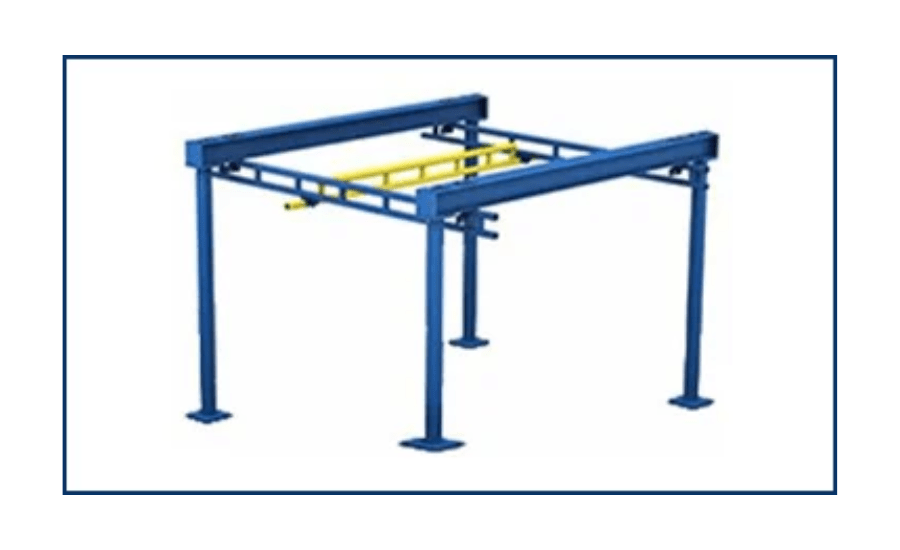
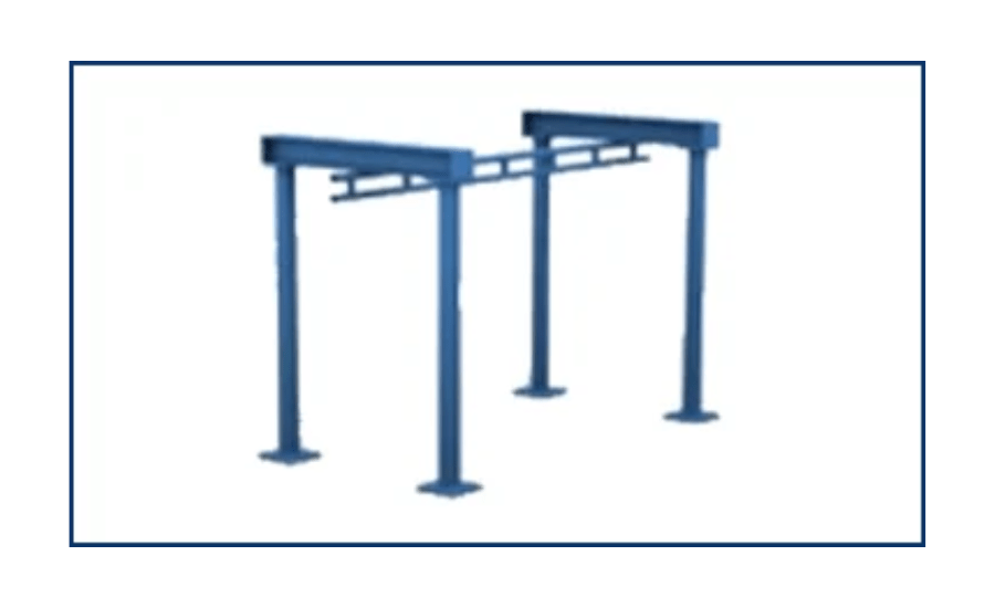
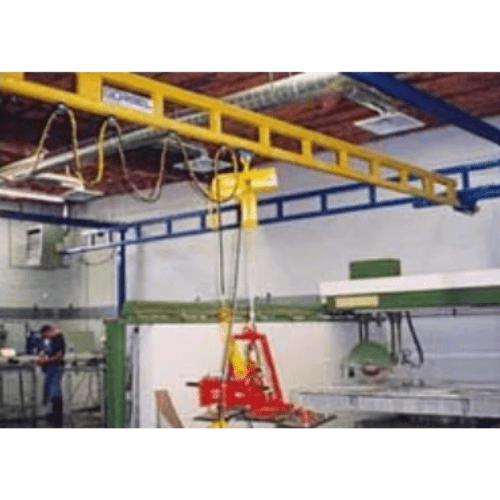
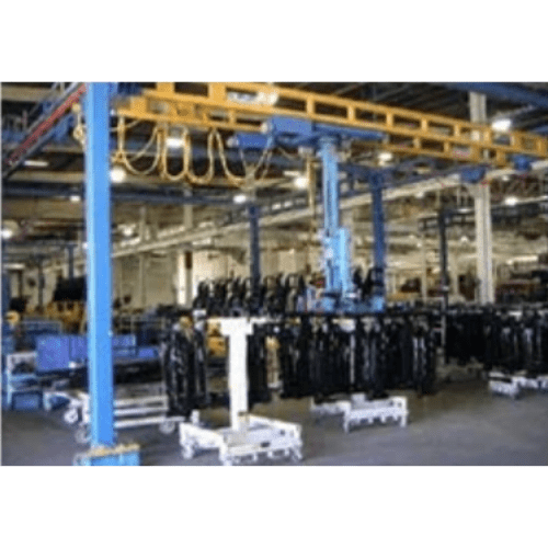
Freestanding Workstation Bridge Cranes
Capacities up to 4,000-lbs.
Bridge spans up to 34’.
10-lbs force will move a 1K load.
5 to 1 design safety factor.
10 year warranty.
Baked on enamel finish.
Power drive available.
Many accessory items available
Stainless steel models available.
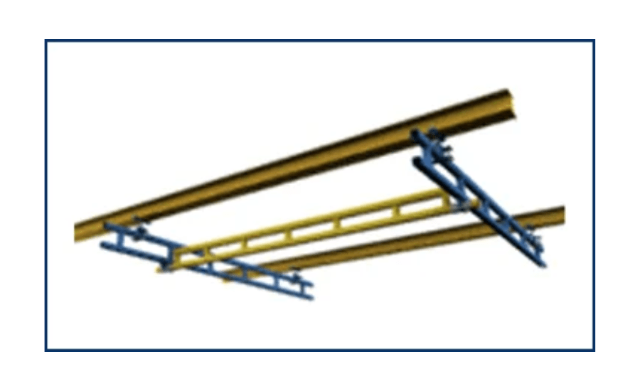
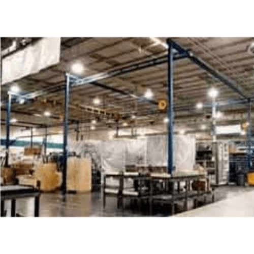
Ceiling Mounted Workstation Bridge Cranes
Capacities up to 4,000-lbs.
Bridge spans up to 34’.
10-lbs force will move a 1K load.
5 to 1 design safety factor.
10 year warranty.
Baked on enamel finish.
Power drive available.
Many accessory items available
Stainless steel models available.
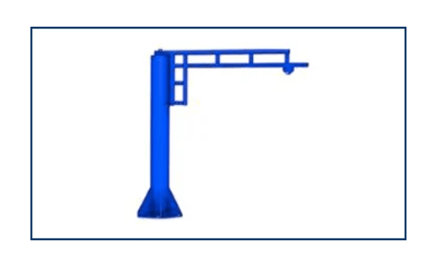
Workstation Jib Cranes
Capacities up to 1,000-lbs.
Boom spans up to 16’.
360° rotation
10-lbs force will move a 1K load.
5 to 1 design safety factor.
10 year warranty.
Baked on enamel finish.
Many accessory items available.
Wall mounted booms available.
Stainless steel models available.
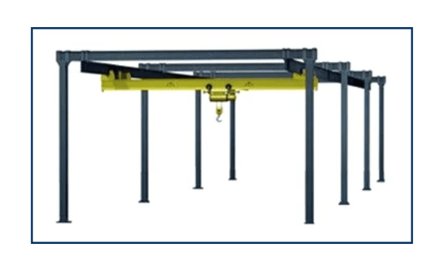
Patented Track Bridge Cranes
Capacities up to 50-tons.
Bridge spans up to 50’.
Power drive functions.
Severe Duty applications.
10 year warranty.
Baked on enamel finish.
Freestanding and building supported systems available
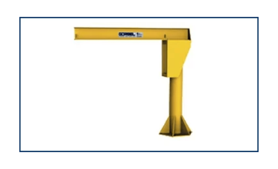
I-Beam Jib Cranes
Capacities up to 5-tons.
Boom spans up to 20’.
360° rotation
Severe duty compliant.
10 year warranty.
Baked on enamel finish.
Powered Rotation available.
Wall mounted booms available
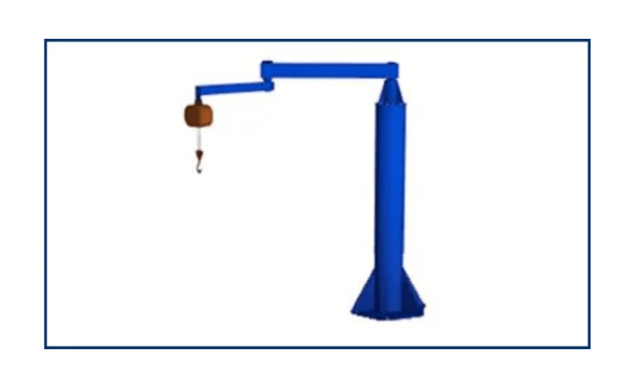
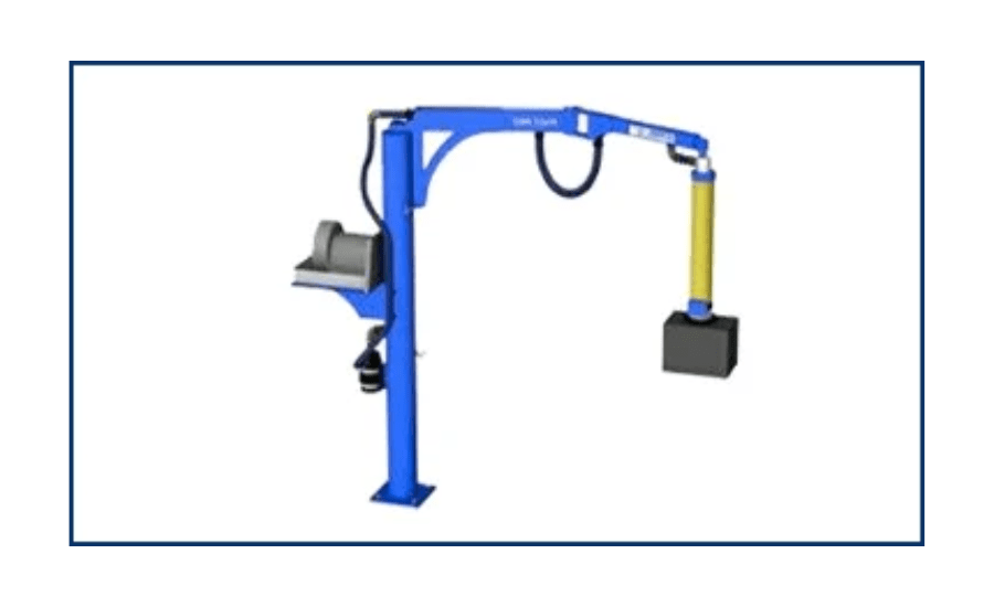
Articulated Jib Cranes
Capacities up to 2-tons.
Boom spans up to 16’.
360° rotation
Reach around abstractions.
Reach through doorways.
10 year warranty.
Baked on enamel finish.
Powered Rotation available.
Wall mounted booms available.
Ceiling mounted configurations available.
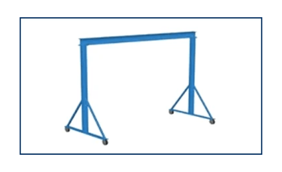
Gantry Cranes
Capacities up to 3-tons.
Bridge spans up to 25’.
Fixed & adjustable height models available.
5 to 1 design safety factor.
10 year warranty.
Baked on enamel finish.
Powered trolley drive available.
Aluminum models available.
Many accessory items available.
Workstation Mono-Rails
Capacities up to 4,000-lbs.
90° curves available.
10-lbs force will move a 1K load.
5 to 1 design safety factor.
10 year warranty.
Baked on enamel finish.
Power drives available.
Ceiling mounted systems available.
Stainless steel models available.
High-Speed Articulated Jib Cranes
Capacities up to 150-lbs.
Boom spans up to 12’.
360° rotation.
Ideally suited for vacuum tube lifters.
Reach around abstractions.
Reach through doorways.
10 year warranty.
Baked on enamel finish.
Wall mounted booms available.
Ceiling mounted configurations available.
How to Select A Workstation Crane
Basic Questions You Need to Consider
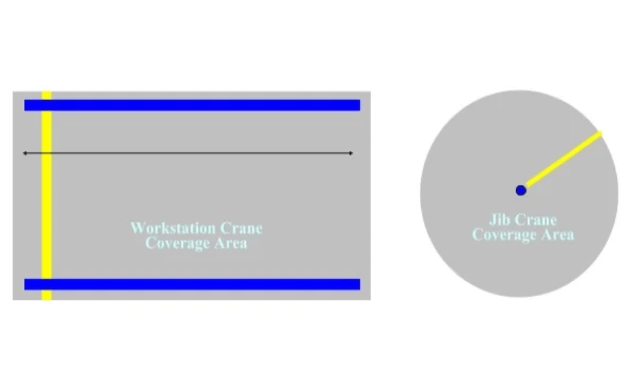
What is the size and shape of the work area you are looking to cover?
Work Station Bridge Cranes offer square/rectangular coverage while Workstation Jib Cranes offer circular coverage.
Is the crane going to be manual or motorized?
When load weight or operational cycle time makes manual bridge or boom movement non-economical, impractical, or unsafe motorized rotation may be the answer
What is the type and extent of the structural support available?
Determine if free standing, ceiling mounted, or wall/column mounted is best for your application
What is the capacity of the load?
“Less is More, Don’t Overcrane” – lifting and moving product that weighs 200 lbs. would only require a 250 lb. bridge – don’t go overboard with a 500 lb. bridge unless you know for sure you will be lifting heavier loads in the not to distant future.
What is the crane’s environment?
In food processing applications and manufacturing plants utilizing harsh chemicals it may be necessary to specify stainless steel or a food grade epoxy coating to protect against corrosion and meet certain industry standards
How will the crane be used in daily operation?
A short description of your handling requirement will help our engineers determine what configuration & accessory items will be needed for our application.
How To Apply Ergonomic
Overhead Workstation Cranes
What Type of Crane Is Most Appropriate?
These questions and answers can help you determine which type of overhead work station crane best meets your needs.
- Bridge cranes cover rectangular areas, while jib cranes cover circular areas.
- Work Station bridge cranes can be floor supported or hung from the ceiling. Jib cranes can be wall or pillar mounted and may require a special foundation.
- An enclosed track workstation bridge crane provides consistent ease of operation over the full range of movement.
- Jib cranes move more easily at the very end of the boom and are more difficult to move as the load approaches the pivot point.
Ease of movement and light weight are key features of enclosed track workstation crane systems. In fact, manual workstation cranes do the job faster than motorized cranes. If the operator cannot control the load throughout the operation (for instance, over a vat, pit, or other inaccessible area), then the crane should be motorized.
- Free standing (floor-supported) systems do not put stress on the building’s overhead structure. Installation is usually more straightforward, and these cranes are also easier to relocate in the future. These systems require a reinforced concrete floor of at least 6 inches.
- With ceiling mounted systems, supporting steel does not interfere with the handling operation. Ceiling mounted systems require a building with an adequate overhead structure to hang the crane.
The general rule is “less is more.”
- Keep capacities to a minimum. Work Station Cranes are designed with an adequate safety factor. If you “over-buy capacity,” the operator will need to move extra bridge dead weight, which would not be a good ergonomic solution.
- Keep bridge lengths to a minimum. The less dead weight an operator has to move, the better. Short bridge lengths are better for higher-cycle production areas. Longer bridges are acceptable for lower-production cycle or maintenance areas.
- Keep bridge heights (trolley saddle) to a minimum- keeping the trolley saddle (TS) height less than 14 feet is desirable because it makes it easier to control and position the load.
- A work cell should be designed so a task can be performed by 90% of the workers.
- A worker should not exceed 33% of his or her capacity; otherwise, the risk of chronic fatigue increases.
Enclosed Track Design Makes for
Easy Movement and Long Life
Both the aluminum and steel Work Station Crane Systems utilize enclosed track that is high in strength and low in weight.
Major Advantages:
- Enclosed track crane are up to three times easier to move than traditional bridge cranes.
- The design virtually eliminates dirt and dust from the rolling surface, thus reducing wear on the wheels of the trolley and end trucks.
- The smooth running surface means lower rolling resistance.
- The low profile of the steel track allows the system to be installed where headroom is a problem.
- The low track weight reduces the applied forces exerted on the supporting structure.
- Long spans allow systems to be installed where support assemblies are infrequent (up to 30 feet with steel truss design). This reduces the possibility of the support columns interfering with the work cell layout.
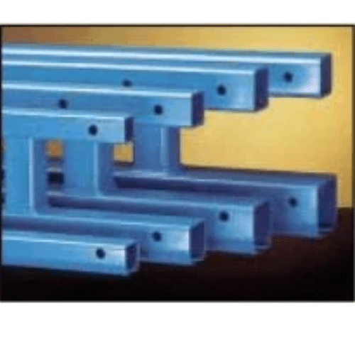
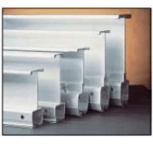
- Four distinct sizes of track — 250, 500, 1000, and 2000 series – enable you to keep bridge weights and costs to a minimum.
TRUSSED STEEL TRACK:
Permits longer spans which allow more flexibility in crane layout.
The trussed series uses the plain steel track profile but is enhanced for longer spans via a built-up truss design. This design increases the span, which decreases the need for frequent hangers. Model numbers start with: GLCS-FS for spans up to 20 feet, GLCSL-FS for spans up to 25 feet, and GLCSLX-FS for spans up to 30 feet. Long spans translate into fewer runway support points, less interference of work cell layout, longer bridge lengths, and free standing capabilities… just another reason why Work Station Cranes are among the most versatile to apply and easiest to install in the industry.
ALUMINUM TRACK:
For use where lower bridge weight and easier movement are required The patented shape of ASE’s aluminum enclosed track provides for low weight, unparalleled spanning capability, and effortless movement. The low weight (up to 44% less than trussed steel track) results in easier movement, which makes for safe, productive, ergonomic work cells. Runway spans up to 20 feet and bridge lengths up to 34 feet meet a wide range of applications. Model numbers start with AL-FS.
Rigid Runways Provide for Superior
Positioning of Loads
Work Station Bridge Cranes are installed so that the runways are rigid. They do not move laterally or longitudinally. In addition, the floating end trucks with horizontal wheels prevent binding. The combination of these design features results in unmatched ease of positioning and ease of movement. The bridge travels smoothly down the runways, and movement is unvarying along the way, no matter where a load is positioned on the bridge. This allows superior load positioning. Another advantage of rigid runways is that runways double as stringers between support columns. This eliminates the need for expensive intermediate support stringers, and it lowers overall installation cost.
Mixed Capacity Bridge Crane Systems
Reduced bridge dead weight equals better ergonomic solutions.
Mixed-capacity systems allow multiple lower capacity bridges to be used on higher capacity runways, provided the equivalent center loads (ECL) are verified at the factory to ensure that runways and hangers are not overloaded. For example, using ASE’s mixed-capacity end trucks, four 500 lb. bridges (utilizing 500 series rail) can be hung from a 2000 lb. runway, allowing side-by-side use of all four bridges without overloading the system. By mixing bridges of various sizes and capacities, mixed-capacity systems offer reduced bridge dead weight, easier movement, and reduced cost.
WARNING: Equipment described in this brochure is not designed for, and should not be used for, lifting, supporting, or transporting humans. Failure to comply with any one of the limitations noted can result in serious bodily injury and/or property damage.
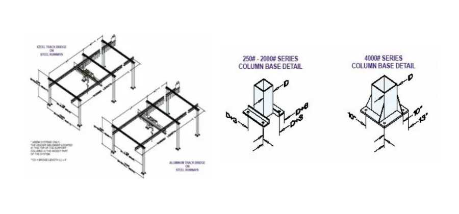
Easy to Install
Free Standing Work Station Bridge Cranes can be installed on any normal 6″ reinforced concrete floor. Each column is anchored by four bolts, thus eliminating the need for field welding. Support columns are designed to AISC specifications. If no movement of the support assemblies is required, then bracing to the building is recommended (not included).
Modular Design
The pre-engineered modular kit design permits easy expansion or relocation. The runway length can be increased by adding runway sections, free standing support assemblies and additional bridges as needed.
What is meant by Rated Capacity?
The rated capacity is the live load that can be lifted by the crane system. The design load for the crane system is based on the rated capacity plus 15% for the weight of the hoist and trolley (capacity _ 1.15) and an additional 25% for impact (capacity _ 1.25) for a total design of capacity _ 1.4 (Note, 25% impact factor is good for hoist speeds up to 50 f.p.m.). For example, a 1000-lb. ASE cranes allows you to pick up a 1000 lb. load provided the hoist weighs 150 lb. or less and the hoist speed is less than 50 feet per minute.
Design load for deflection calculations is based on the rated capacity plus 15% for the weight of the hoist and trolley (capacity _ 1.15). Under no conditions should the crane be loaded beyond its rated capacity. Work Station Cranes meet or exceed the ANSI B30.11 specifications for under hung bridge cranes.
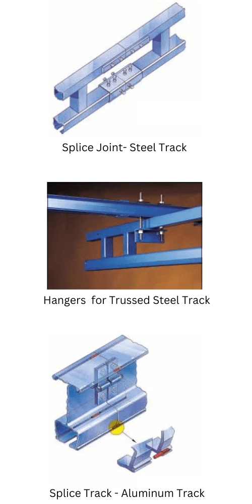
SPLICE JOINTS FOR STEEL TRACK
A splice joint is used to join track sections together and enable the installer to quickly and properly align the joined sections of track. Adjusting bolts are provided on the splice joint for leveling and aligning.
Hangers for Trussed Steel Track
Hangers for steel runways are included with each assembly as shown. The runways are flush mounted under the free standing support assemblies via spine clamp angles, B7 alloy threaded rods, and the appropriate hardware.
SPLICE JOINTS FOR ALUMINUM TRACK
Patented splice joints for aluminum track allow for precision alignment. The aluminum track is extruded with four patented alignment slots. Four precision-ground pins are provided to accurately align runway sections, which provides for a smoother transition of wheels over the splice joint than is possible with bolted connections. In addition, clamp fasteners attach to the vertical web of the track to pull the track together and keep it from separating.
HANGERS FOR ALUMINUM TRACK
Standard hangers for aluminum runways are included with each assembly shown. The runways are flush mounted under the free standing support assemblies via beam clips, B7 alloy threaded rods, and the appropriate hardware.
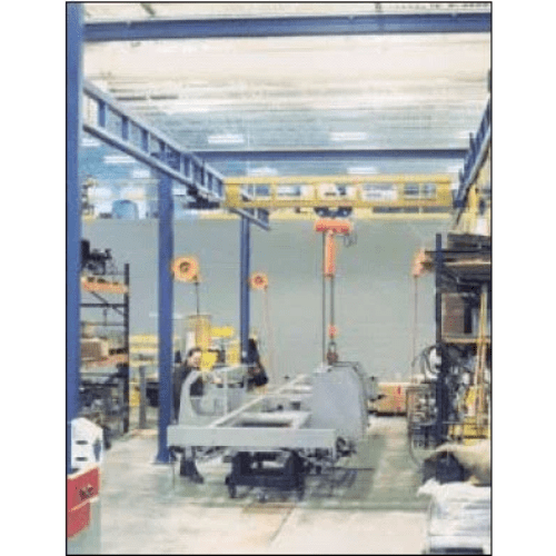
FREE STANDING WORK STATION BRIDGE CRANES
Steel Runways With Steel or Aluminum Bridge Isometric View
Free Standing Work Station Crane kits include: bridge, runways, the appropriate number of support assemblies, hoist trolley, end trucks, end stops, flat wire festooning, festoon gliders (festoon trolleys on steel runway lengths greater than 63′ and all aluminum systems), festoon stack-up section, splice joints and hanger brackets.
Hoist and anchor bolts provided by others.
Workstation Crane Component Parts
Component Parts of a WorkStation Crane
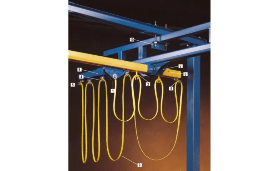
1. HOIST TROLLEYS
Hoist trolleys provide the connection between the lifting device and the bridge. The trolleys are designed for effortless movement along the bridge. The stamped body fits most rigid hook or eye lifting devices.
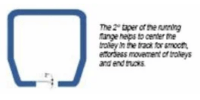
- Wheels are tapered to match the 2° taper of the track. This reduces rolling resistance and wheel wear. Wheels contain ball bearings that are sealed and lubricated for life.
- Trolleys are designed to operate in temperatures from +5°F to +200°F.
- All trolleys meet or exceed the ANSI B30.11 specification for under hung bridge cranes.
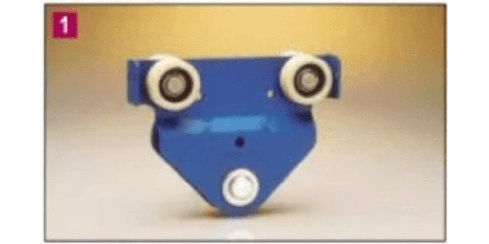
2. END TRUCKS
End trucks provide the connection between the bridge and runways. They are designed for effortless movement along the runway.
- Wheels are tapered to match the 2° taper of the track, which reduces rolling resistance and wheel wear. Wheels contain ball bearings that are sealed and lubricated for life.
- Two horizontal wheels center the end truck within the runway which prevents binding of the bridge. As a result, the position of the load on the bridge has little effect on the amount of force needed to move the bridge along the runway.
- Any slight runway track misalignment is taken up by the bridge floating in one end truck, while the other end truck is firmly clamped to the bridge.
- All end trucks meet or exceed the ANSI B30.11 specification for under hung bridge cranes.
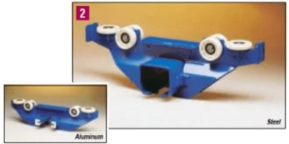
3. FESTOON GLIDERS
Festoon gliders are used to support flat cable along the runway and bridge, and they are standard on steel runways of 63 feet or less. No tools are required to attach the festooning to the gliders.
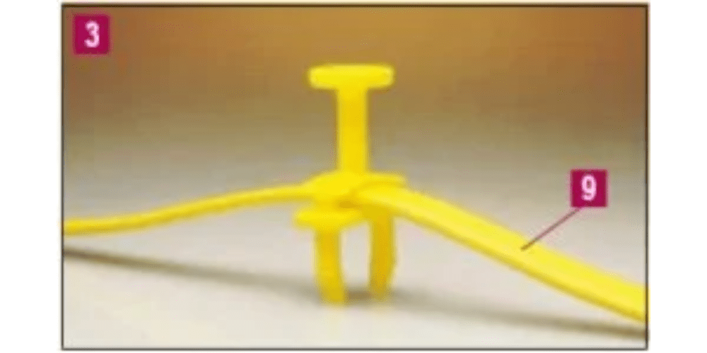
4. FESTOON TROLLEYS
Festoon trolleys (optional) are used to support flat cable or air hose along the runway or bridge. The trolleys have four wheels and a pivoting festoon saddle support. They are ideally suited for long runways (greater than 63 feet) or with round cable or air hose. With runways greater than 63 feet or with an all aluminum system, festoon trolleys are standard. Special festoon trolleys for vacuum hose are also available.
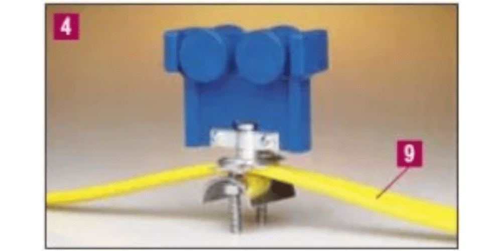
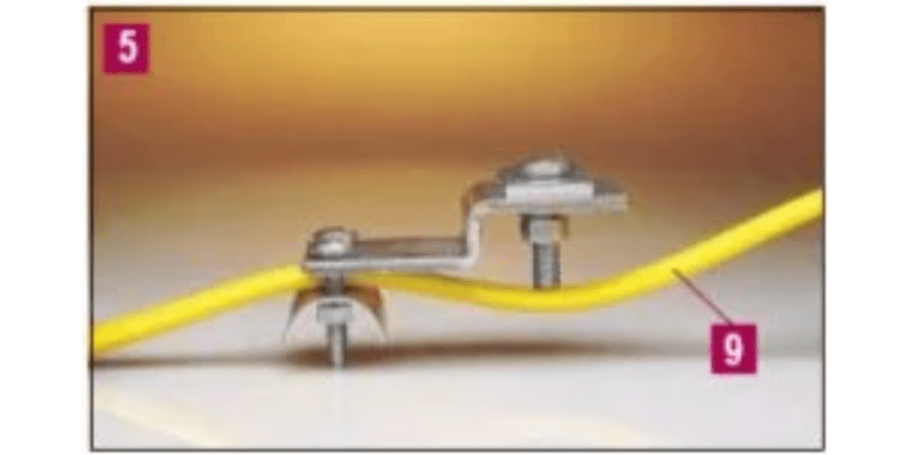
5. FESTOON CLAMPS
Festoon clamps anchor the festooning at the start of the runway and bridge. They also prevent the festoon gliders from exiting the track and they can provide a redundant stop for the end trucks and trolley.
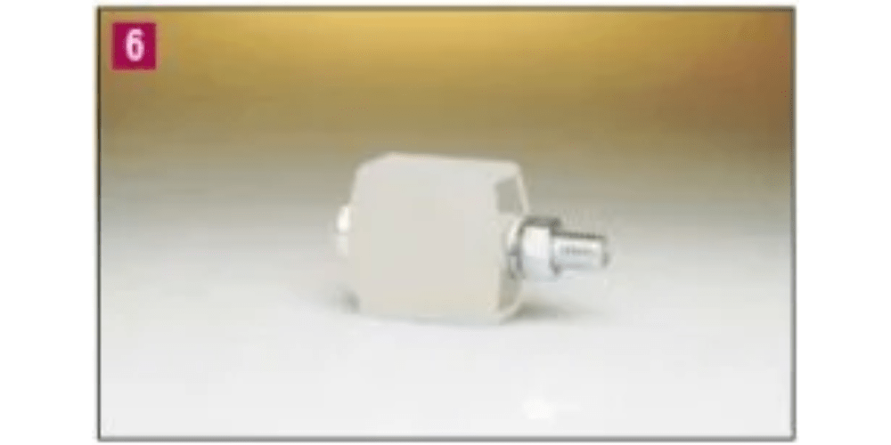
6. END STOP BUMPERS
High-impact molded end stop bumpers are provided on all runways and bridges to prevent the end trucks and trolley from exiting the track. The bumpers are bolted to the track to physically limit the travel of the end truck and trolley.
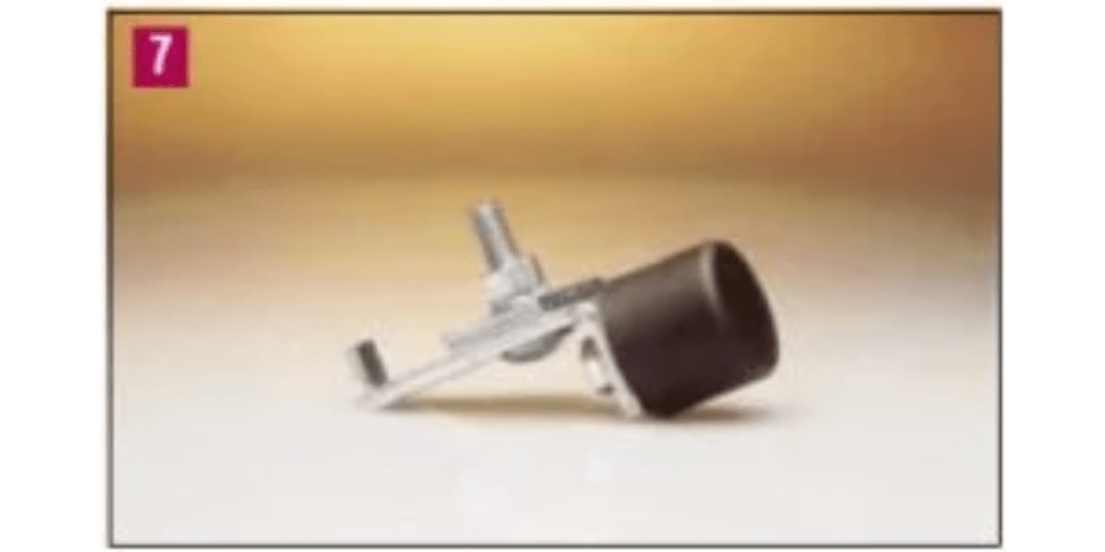
7. UNIVERSAL BUMPERS (not shown on main layout)
A universal bumper can be used as a secondary end stop, either internally or externally.
Call 800-245-2163 for pricing & additional information.
8. STACK SECTIONS
A stack section at one end of a runway serves as an extension that allows festoon carriers to be stored on the end of the runway without reducing crane coverage.
9. FLAT CABLE AND/OR AIR HOSE
A flat cable festooning system is included in all Work Station Bridge Cranes. Plenty of cable is provided for 3 foot loops on the runway and 1 foot 6 inch loops on the bridge. Optional air hose is also available and is supported by optional festoon trolleys. Work Station Cranes can utilize optional conductor bar electrification, but this results in an increase up to 40% of the amount of effort required to move the system.
10. HANGER ASSEMBLIES
Each Work Station Bridge Crane is provided with the appropriate number of hanger assemblies, based on the number of support assemblies shown in this document’s dimensional pages.